Graphically creating well pads
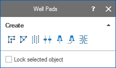
Use the last three tools in the Create section of the floating palette for wells and well pads click to enlarge
You can graphically create well pads in your 3D view using the well pad tool  in the Create section of the Editing Tools floating palette (select Workspace > Tools > Editing Tools on the right of the Strip to open this).
First display the location where you want the well to be in your 3D view. Click the Create Well Pad tool and then on a surface in your 3D view to place the well pad.
Enter your details about the well pad on the Well Pad Preliminary form that opens.
After entering your data and clicking OK on the Well Pads form, the well pad appears in your 3D view. The designs of the wells in the well pad appear in a folder of the same name as the well pad under Well Data > Well Designs in the JewelExplorer. The wells themselves (calculated from the well designs) appear in a folder with the same name under Well Data > Wells.
The tools for positioning a well pad become available when you select the well pad in the JewelExplorer. You can use these tools to reposition your well pad, see Graphically editing wellpads. Once you have positioned your well pad you can work on individual wells and well targets with the different tools on the floating palette, see Graphically editing wells.